
Product Details
Place of Origin: China
Brand Name: REXROTH
Model Number: A11VO190
Certifiion: CE ISO 9001
Payment & Shipping Terms
Minimum Order Quantity: 1
Price: NIGOTIATION
Packaging Details: standard box
Delivery Time: 5 work days
Payment Terms: T/T
Supply Ability: 1000/month
Usage: |
Hydraulic Piston Pump |
Appliion: |
Hydraulic System,hydraulic Pumps,exvaor |
Structure: |
Piston Pump |
Power: |
Hydraulic |
Pressure: |
High Pressure |
Fuel: |
Hydraulic |
Theory: |
Hydraulic Pumps |
Standard Or Nonstandard: |
Standard |
Color: |
Black Or As You Need |
Material: |
Cast Iron |
Product Name: |
Hydraulic Pumps,Genuine Rexroth Hydraulic Gear Pump |
Warranty: |
1 Year,12 Months,one Year |
Condition: |
100%new,New Rexroth Pump,OEM New & Original,Oringal New |
Feature: |
High Efficiency,Long Life |
Type: |
Hydraulic Pump Rexroth |
Name: |
Rexroth Piston Pump |
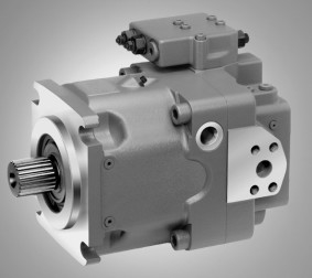
Rexroth Axial piston pump A11VO A11VLO 40/60/75/95/110/130/145/160/75/190/200/210/250/260/280
![]()
| R902552360 | A11VO145DRS0A00/40MLVD4T11EA3S20-0 |
| R902546189 | A11VO145DRS0A00/40MLVD4T21EU0000-0 |
| R902545391 | A11VO145DRS0A00/40MRVD4T21EU0000-0 |
| R902561183 | A11VO145DRS0A00/41MRVD4T1PU0’981798*EW*& |
| R902559214 | A11VO145DRS0A0K/41MRVD4T1PU0’981798*EW*& |
| R902560737 | A11VO145E2S0APK/40MRVD4A21ED4T10-S |
| R902543845 | A11VO145LRDRH4B00/40MRVD4A21EB3S40-0 |
| R902549440 | A11VO145LRDRH4B00/40MRVD4A21EB3S40-S |
| R902557558 | A11VO145LRDRH4B00/41MRVD4A2P’981798*EW*& |
| R902557568 | A11VO145LRDRH4B00/41MRVD4A2P’981798*EW*& |
| R902540517 | A11VO145LRDRS0A00/40MRKD4T11EU0000-0E |
| R902557557 | A11VO145LRDRS0A00/41MRKD4T1P’981798*EW*& |
| R902547428 | A11VO175DRS0A00/40MRVE4T21EU0000-0 |
| R902551428 | A11VO175E2S0APB/40MRVE4T21ED4T10-S |
| R902560739 | A11VO175E2S0APK/40MRVE4A21ED4T10-S |
| R902536680 | A11VO175L4S0AP0/40MRVE4A21EA3S20-0 |
| R902533186 | A11VO210DGT8AP0/40MLVE4A21EB3S40-S |
| R902551424 | A11VO210E2S0APB/40MRVE4T21ED4T10-S |
| R902560738 | A11VO210E2S0APK/40MRVE4A21ED4T10-S |
| R902560736 | A11VO210E2S0APK/40MRVE4A21EE4A20-S |
| R902549470 | A11VO210E4S0AP0/40MRVE4T11EU0000-S |
| R902550095 | A11VO210E4S0AP0/40MRVG3A21EE4T10-S |
| R902549097 | A11VO210L4S4AP0/40MRVG3A21EC4S70-0 |
| R902551426 | A11VO280LRDGE2CPB/40MRVE4T11EU000D |
| R902553790 | A11VO280LRDRH3B00/40MRVE4A41EB3S40-0 |
| R902553766 | LA11VO110E2CPK/40MRVD4A11EB3S50-0 |
| R902545915 | LA11VO110L4DGE2APK/40MLVD4A11EC4V80-0 |
| R902539291 | LA11VO110MGT6APB/40MLVD4A11EU0000-0 |
| R902561182 | LA11VO145DRS0A00/41MRVD4T1PU’981798*EW*& |
| R902559213 | LA11VO145DRS0A0K/41MRVD4T1PU’981798*EW*& |
| R902545400 | LA11VO145E1BPK/40MRVD4T11EU0000-0 |
| R902545446 | LA11VO145E2BPK/40MRVD4A21EA7S30-SE |
| R902548438 | LA11VO145E2S0APK/40MRVD4A21ED4T10-S |
| R902543550 | LA11VO145L3DRS0CP0/40MRVD4A21EU0000-0 |
| R902545914 | LA11VO145L4S0APK/40ML+AZPF-11-019L |
| R902557554 | LA11VO145L4S0APK/41ML+AZPF-1’981798*EW*& |
| R902536141 | LA11VO145L4S4AP0/40MRVD4A21EA7S30-SE |
| R902543143 | LA11VO145L4S4AP0/40MRVD4A21EA7S30-SE |
| R902537382 | LA11VO145L4S4AP0/40MRVD4A21EA7S30-SE |
| R902557542 | LA11VO145L4S4AP0/41MRVD4A2EA’981798*EW*& |
| R902557541 | LA11VO145L4S4AP0/41MRVD4A2EA’981798*EW*& |
| R902549105 | LA11VO145LRDRH3A00/40MRVD4A21EU0000-0 |
| R902560488 | LA11VO175E2BPK/41MRVE4A2EA7S’981798*EW*& |
| R902494997 | LA11VO175E2S0APK/40MRVE4A21ED4T10-S |
| R902541726 | LA11VO210E2S0APK/40MRVE4A21ED4T10-S |
| R902536177 | LA11VO210E2S0APK/40MRVE4A21EE4A20-S |
| R902536144 | LA11VO210E4S0APB/40MRVE4T21EE4T10-SE |
| R902543448 | LA11VO210L4S4AP0/40MRVE4A21EA7S30-SE |
| R902536180 | LA11VO210L4S4AP0/40MRVE4A21EA7S30-SE |
| R902537058 | LA11VO210L4S4APK/40MRVE4A21EA7S30-S |
| R902536775 | LA11VO210L5E2AP0/40DR+A4VG71DWD1/32R+& |
| R902541720 | LA11VO210L5E2AP0/40DRVG3A21EC3Z80-0 |
Technical Data
Table of values (theoretical values, without efficiency and tolerances; values rounded)
Rexroth A11VO A11VLO Pump |
Des. | A11VLO40 | A11VLO60 | A11VLO75 | A11VLO95 | A11VLO130 | A11VLO145 | A11VLO190 | A11VLO260 |
| A11VO40 | A11VO60 | A11VO75 | A11VO95 | A11VO130 | A11VO145 | A11VO190 | A11VO260 | ||
| Disp. Vg max Vg min |
In3/rev. | 2.56 | 3.57 | 4.52 | 5.71 | 7.93 | 8.84 | 11.78 | 15.87 |
| cm3 | 42 | 58.5 | 74 | 93.5 | 130 | 145 | 193 | 260 | |
| cm3 | 0 | 0 | 0 | 0 | 0 | 0 | 0 | 0 | |
| Speed | rpm | 3000 | 2700 | 2550 | 2350 | 2100 | 2200 | 2100 | 1800 |
| rpm | 3500 | 3250 | 3000 | 2780 | 2500 | 2500 | 2100 | 2300 | |
| Flow | g/m | 33.3 | 41.7 | 49.9 | 58.1 | 72.1 | 84.3 | 107 | 123.6 |
| l/min | 126 | 158 | 189 | 220 | 273 | 319 | 405 | 468 | |
| Power at | hp | 99.2 | 123.4 | 147.5 | 171.7 | 213.2 | 249.4 | 316.5 | 366.1 |
| kW | 74 | 92 | 110 | 128 | 159 | 186 | 236 | 273 | |
| Torque at | lb-ft | 172.6 | 240.4 | 303.9 | 384.3 | 534 | 596 | 792.9 | 1068 |
| Nm | 234 | 326 | 412 | 521 | 724 | 808 | 1075 | 1448 | |
| Rotary stiffness | lb-ft/rad. | 64512 | 79574 | 105548 | 14883 | 230417 | 230417 | 282702 | 482244 |
| Nm/rad. | 87467 | 107888 | 143104 | 196435 | 312403 | 312403 | 383292 | 653835 | |
| lb-ft/rad. | 43035 | 63658 | 75173 | 128117 | 174700 | 174700 | 191599 | 259628 | |
| Nm/rad. | 58347 | 86308 | 101921 | 173704 | 236861 | 236861 | 259773 | 352009 | |
| lb-ft/rad. | 54931 | 75556 | 92640 | – | – | – | 222691 | 418282 | |
| Nm/rad. | 74476 | 102440 | 125603 | – | – | – | 301928 | 567115 | |
| Moment of inertia for rotary group | lbs-ft2 | 0.1139 | 0.1946 | 0.2729 | 0.4105 | 0.7546 | 0.8092 | 1.3052 | 2.0835 |
| kgm2 | 0.0048 | 0.0082 | 0.0115 | 0.0173 | 0.0318 | 0.0341 | 0.055 | 0.0878 | |
| Angular acceleration | rad./s2 | 22000 | 17500 | 15000 | 13000 | 10500 | 9000 | 6800 | 4800 |
| Filling capacity | gal | 0.29 | 0.36 | 0.49 | 0.55 | 0.77 | 0.77 | 1 | 1.22 |
| L | 1.1 | 1.35 | 1.85 | 2.1 | 2.9 | 2.9 | 3.8 | 4.6 | |
| Mass | lbs | 71 | 88 | 99 | 117 | 145 | 168 | 209 | 276 |
| kg | 32 | 40 | 45 | 53 | 66 | 76 | 95 | 125 |
Hydraulic fluid
We request that before starting a project detailed information about the choice of pressure fluids and appliion conditions are taken from our alogue sheets RE 90220 (mineral oil), RE 90221 (environmentally acceptable hydraulic fluids) and RE 90223 (fire resistant hydraulic fluids, HF). When using HF- or environmentally acceptable hydraulic fluids possible limitations for the technical data have to be taken into consideration. If necessary please consult our technical department (please indie type of the hydraulic fluid used for your appliion on the order sheet). The operation with HFA, HFB and HFC hydraulic fluids requires additional special measures.
Details regarding the choice of hydraulic fluid
The correct choice of hydraulic fluid requires knowledge of the operating temperature in relation to the ambient temperature: in an open circuit the tank temperature. The hydraulic fluid should be chosen so that the operating viscosity in the operating temperature range is within the optimum range (νopt.) – see the shaded area of the selection diagram. We recommended that the higher viscosity class be selected in each . Example: At an ambient temperature of X°C an operating temperature of 60°C is set. In the optimum operating viscosity range (νopt; shaded area) this corresponds to the viscosity classes VG 46 and VG 68; to be selected: VG 68. Please note: The drain temperature, which is affected by pressure and speed, is always higher than the tank temperature. At no point in the system may the temperature be higher than 115°C.
Charge pump (impeller)
The charge pump is a circulating pump with which the A11VLO (size 130...260) is filled and therefore can be operated at higher speeds. This also simplifies cold starting at low temperatures and high viscosity of the hydraulic fluid. Tank charging is therefore unnecessary in most s. A tank pressure of a maximum 2 bar is permissible with charge pump.
drain pressure
The drain pressure at the ports T1 and T2 may be a maximum of 17.5 psi (1.2 bar) higher than the inlet pressure at the port S but not higher than PL abs. max 30 psi (2 bar). An unrestricted, full size drain line directly to tank is required.
Temperature range of the shaft seal ring
The FKM shaft seal ring is permissible for drain temperatures of -13 °F to 240 °F (-25 °C to +115 °C).
Note: For appliions below-13 °F (-25 °C), an NBR shaft seal ring is necessary (permissible temperature range: -40 °F to 194 °F (-40 °C to +90 °C).
DR Constant Pressure Control
The constant pressure control maintains the pressure in a hydraulic system constant within its control range in spite of changing pump flow requirements. The variable pump supplies only the volume of fluid required by the consumer. Should operating pressure exceed the set pressure, the pump is automatically swiveled back to a smaller angle and the deviation in control corrected.
In un-operated (zero pressure) condition, the pump is swiveled to its starting position (Vg max) by means of a control spring.
LR Constant Power Control
The constant power control controls the output volume of the pump in relation to the operating pressure so that, at a constant drive speed, the preset drive power is not exceeded.
Operating pressure applies a force on a piston within the control piston on to a rocker arm. An externally adjustable spring force is applied to the other side of the rocker arm to determine the power setting. Should the operating pressure exceed the set spring force, the pilot control valve is operated via the rocker arm, allowing the pump to swivel towards zero output. This in turn reduces the effective moment on the arm of the rocker, thus allowing the operating pressure to rise in the same ratio by which the output flow is reduced.
LRDS Power control with pressure cut-off and load sensing
The load sensing control is a flow control option that operates as a function of the load pressure to regulate the pump displacement to match the actuator flow requirement.
The flow depends here on the cross section of the external sensing orifice fitted between the pump outlet and the actuator. The flow is independent of the load pressure below the power curve and the pressure cut-off setting and within the control range of the pump.
The sensing orifice is usually a separately arranged load sensing directional valve (control block). The position of the directional valve piston determines the opening cross section of the sensing orifice and thus the flow of the pump.
The load sensing control compares pressure before and after the sensing orifice and maintains the pressure drop across the orifice (differential pressure) and with it the pump flow constant.
LRC Override with cross sensing
Cross sensing control is a summation power control system, whereby the total power, of both the A11VLO pump or A11VO pump and of a same size A11VO or A11VLO pump power controlled pump mounted onto the through drive, are kept constant.
If a pump is operating at pressures below the start of the control curve setting, then the surplus power not required, in a critical up to 100 %, becomes available to the other pump. Total power is thus divided between two systems as demand requires.
Any power being limited by means of pressure cut-off or other override functions is not taken into account.
Half side cross sensing function When using the LRC control on the 1st pump A11VO or A11VLO pump and a power-controlled pump without cross sensing attached to the through drive, the power required for the 2nd pump is deducted from the setting of the 1st pump. The 2nd pump has priority in the total power setting. The size and start of control of the power control of the 2nd pump must be specified for rating the control of the 1st pump.
HD Hydraulic Control, Pilot Pressure Related
The pilot pressure related hydraulic control allows steeples setting of the pump displacement in relation to pilot pressure. Control is proportional to the pilot pressure applied to port Y (max. 40 bars). A pressure of 30 bars is needed for the control. The oil required for this is taken either from the high pressure or from the external adjustment pressure at port G (≥ 30 bar).
EP Electrical Control with Proportional Solenoid
Electrical control allows steeples and programmable setting of the pump displacement. Control is proportional to solenoid force (current strength). The control force at the control piston is generated by a proportional solenoid valve.
A 12V DC (EP1) or a 24V DC (EP2) supply is required for the control of the proportional solenoid.